 dsale@topsfp.com
 العربية
 English
 русский
 español
 中文
中文



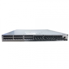
NVIDIA MMA4Z00-NS400: 400Gb/s OSFP SR4 Transceiver Planning Guide
The NVIDIA MMA4Z00-NS400 is a single-port 400 Gb/s OSFP short-reach optical transceiver for selected NVIDIA InfiniBand and Ethernet environments. It is not a general-purpose 400G part that can be substituted solely by matching speed and connector shape. A reliable deployment begins with the exact system topology, host adapter or switch type, fiber plant, connector polish, and firmware support. This guide summarizes the published characteristics of the MMA4Z00-NS400 and the questions that should be answered before it is introduced into an AI or high-performance-computing fabric.
Published interface and optical characteristics
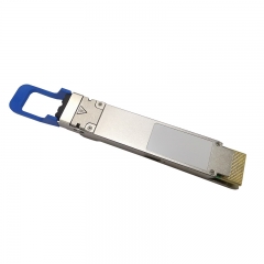
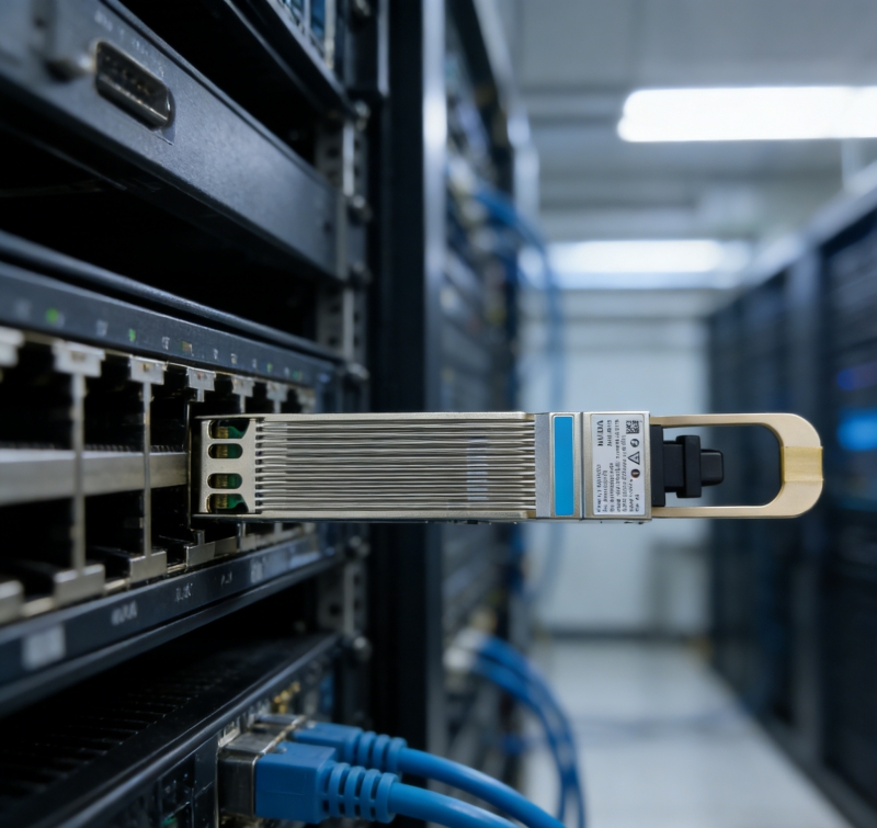
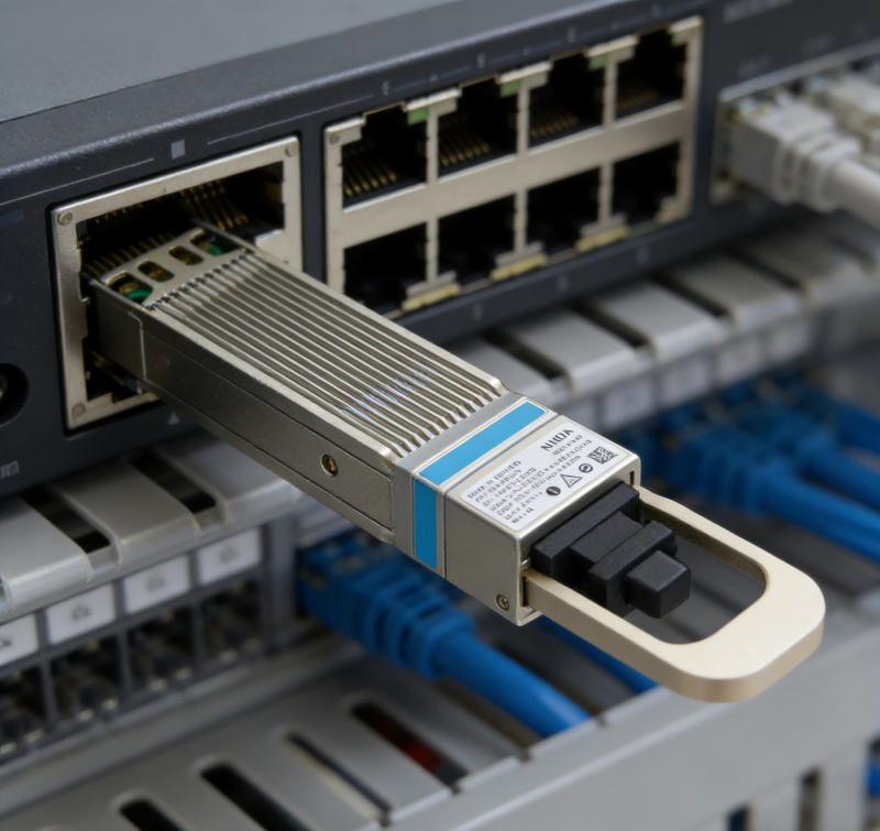
NVIDIA identifies MMA4Z00-NS400 as a 400 Gb/s, single-port, flat-top OSFP SR4 multimode transceiver. It uses four 100G-PAM4 electrical and optical lanes, 850 nm VCSEL optics, and one MPO-12/APC optical connector. The SR4 design is intended for parallel multimode links rather than duplex links. NVIDIA documents a maximum reach of 30 metres over OM3 multimode fiber and 50 metres over OM4 multimode fiber, with the stated 50-metre figure assuming two optical patch panels in the link. Link design should always follow the applicable loss budget and system documentation rather than treating a maximum reach as a guaranteed installation distance.
The connector detail is critical. An MPO-12/APC interface uses angled physical contact; its green connector shell distinguishes it from the aqua-colored Ultra Physical Contact multimode interface. APC and UPC connectors are not interchangeable. Check both patch leads and panel adapters before installation, and verify fiber polarity as part of the end-to-end path. A correct-looking MPO connector can still create a failed or unstable link if the polish type, key orientation, polarity method, or lane mapping is wrong.
Where this module fits in an AI fabric
The part is designed for NVIDIA networking deployments in which a compatible ConnectX-7 OSFP adapter links to a suitable 400G or 2x400G InfiniBand or Ethernet switch configuration. NVIDIA states that the module firmware supports both InfiniBand and Ethernet and is enabled according to the protocol of the attached switch. That protocol flexibility is useful, but it does not remove the requirement to confirm the exact adapter, switch operating mode, firmware version, cable or transceiver combinations, and supported software release.
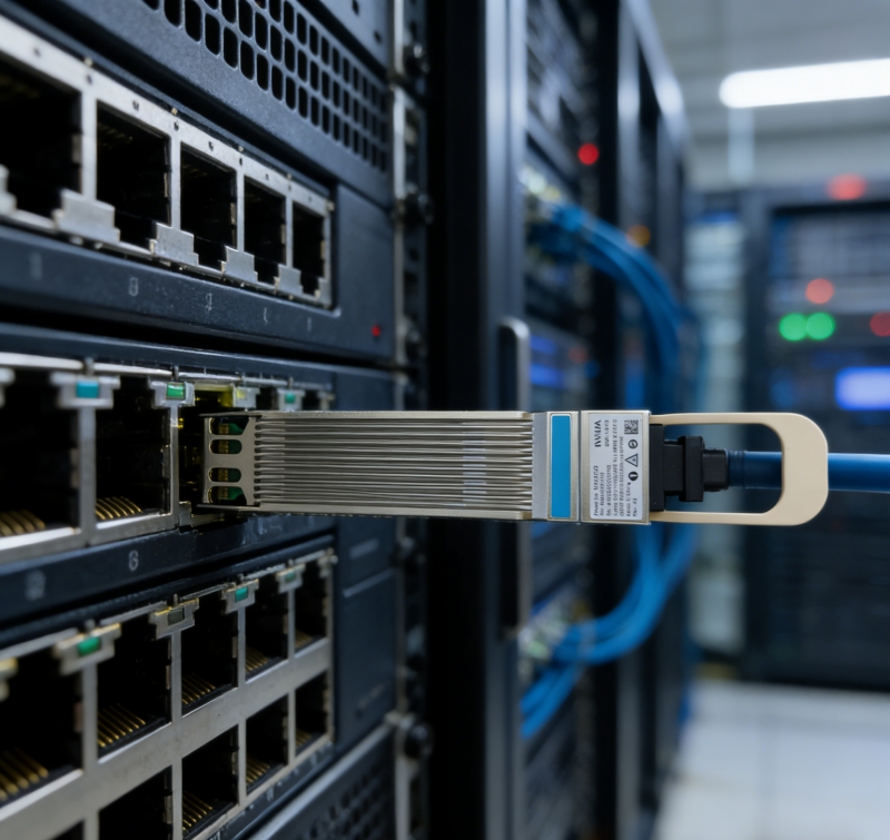
In practical terms, this is an east-west fabric component. Its purpose is to carry low-latency, high-throughput traffic between servers and switching layers rather than to solve every network connection in a data center. The fabric design must account for the number of GPU servers, oversubscription policy, storage traffic, management traffic, congestion-control settings, and growth plan. Select the transceiver only after the topology is stable; changing it later can affect cabling, airflow, power, and rack work.
Reach, fiber, and breakout planning
For a direct 400G SR4 connection, calculate the route length from the actual patching plan, not a straight-line rack distance. Include equipment patch cords, structured cabling, panel connections, slack, and future service loops. Clean every connector before it is mated, inspect it with suitable optical-fiber tools, and protect unused optical interfaces. Multimode links are sensitive to loss and contamination; disciplined installation is more cost-effective than repeated troubleshooting after production cutover.
NVIDIA also documents a 200 Gb/s operating arrangement in certain compatible splitter topologies: when two channels are active through a 1:2 splitter-fiber connection, the module can operate as a 200 Gb/s NDR200 device and reduces its maximum power specification. This is a specific supported design, not a generic instruction to attach any breakout cable. Confirm the switch-side transceiver, splitter model, connector type, host adapter, protocol, and validated matrix before planning such a connection. A quotation should state both endpoints and the full cable path, not only the module part number.
Thermal, power, and mechanical considerations
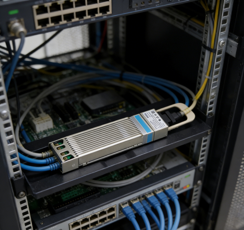
NVIDIA lists a maximum power consumption of 8.5 W when all four channels are active and 5.5 W when operating with two channels in the described 200G mode. The device uses a single 3.3 V supply, is hot-pluggable, RoHS compliant, CMIS 4.0 compliant, and is specified for a 0°C to +70°C case temperature range. These values help the system designer, but the complete thermal condition is set by the switch or adapter cage, adjacent optics, airflow direction, inlet temperature, and fan policy.
The flat-top OSFP shell is intended to work with the cooling arrangement of supported ConnectX-7 cages. Do not assume that a flat-top versus finned-top form factor is cosmetic. A physical fit may still have inadequate clearance or cooling in another system. Before deployment, check the host’s official compatibility list and the cage mechanical guidance. During burn-in, record transceiver temperature, link error counters, FEC statistics, and system alarms at representative load.
Commissioning checklist
First, record the exact part number, serial number, host model, operating system, driver, firmware release, and port configuration. Second, compare the actual switch and adapter configuration to the vendor’s supported topology. Third, inspect and clean the MPO-12/APC path, confirm fiber grade and length, and label both endpoints. Fourth, bring up the link at the intended speed and protocol, then verify lane status, FEC, error counters, and traffic tests. Finally, document the result so that a later swap or expansion can be completed without guessing.
Conclusion
MMA4Z00-NS400 is a clearly defined 400G multimode OSFP SR4 component for compatible NVIDIA AI and HPC networking environments. Its 4x100G-PAM4 design, MPO-12/APC interface, 30-metre OM3 reach, and 50-metre OM4 reach make it suitable for short-reach parallel-fiber links when the complete system is validated. The safest procurement and deployment process is compatibility-first: identify both endpoints, confirm the supported topology and firmware, specify the complete fiber path, and verify link health before workloads move into production.
