 dsale@topsfp.com
 العربية
 English
 русский
 español
 中文
中文



Optical Fiber Communication: A Modern Network for Moving Information
Stories of urgent deliveries are often used to describe the human desire for faster communication. The “litchi express” is a useful metaphor for that desire, but modern optical networks operate on a very different principle. Instead of moving a physical object from place to place, a fiber-optic link carries encoded information as pulses of light through carefully designed glass fiber. This makes it possible to connect servers, campuses, data centers, carriers, and regions with high capacity and predictable performance when the full path is designed and maintained correctly.
Optical fiber is not magic, and “the speed of light” is not the whole story. Light travels more slowly in glass than in a vacuum, and the user experience of an application also includes the time required for switching, routing, serialization, buffering, storage access, and software processing. Even so, fiber is a foundational medium for modern digital infrastructure because it can transport large volumes of information over long distances while remaining resistant to electromagnetic interference and supporting a wide range of network architectures.
How a fiber-optic link carries data
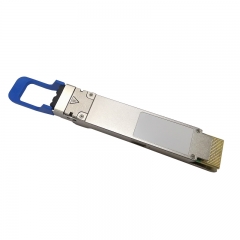
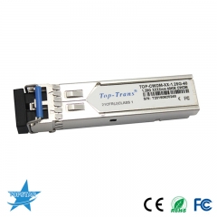
A complete fiber link has several elements. At one end, an optical transceiver or other active interface converts an electrical signal from a switch, server, router, or storage device into a modulated optical signal. That light is coupled into a fiber path, which may include patch cords, distribution panels, splices, and structured cabling. At the receiving end, another optical interface converts the light back into an electrical signal that the attached equipment can process. The link is successful only when every element is compatible and the overall optical loss remains within the supported budget.
The fiber itself contains a core and cladding engineered to guide light. Single-mode fiber is commonly used for long-distance and many higher-reach applications, while multimode fiber is commonly used for shorter-reach connections inside buildings and data centers. These are general categories, not interchangeable descriptions. The transceiver’s wavelength, modulation, reach specification, connector type, and supported fiber grade determine the correct combination. A module designed for one medium should not be installed on another simply because the connector appears to fit.
Why fiber matters for modern infrastructure
Digital services create continuous demand for reliable data movement. Cloud platforms, enterprise applications, AI workloads, video collaboration, storage replication, telecommunications, and industrial systems all depend on networks that can carry more traffic without becoming fragile or difficult to operate. Fiber provides the physical layer for many of these services. It can be deployed as a short patch connection in a rack, a building backbone, a campus link, a metro connection, or a carrier route spanning much greater distances.
Capacity is one reason fiber is important, but it is not the only one. A well-designed fiber installation supports orderly growth. Organizations can plan cable pathways, labeling, cross-connects, spare capacity, and documented routes so that a new server, switch, or rack can be added without rebuilding the entire plant. This planning reduces the risk of accidental outages and makes it easier to identify a connection when troubleshooting is required.
Selection begins with the equipment and the path
When planning a fiber link, begin with both endpoints. Identify the exact switch, router, server adapter, storage port, or other host interface. Confirm the required speed, form factor, and supported transceiver or cable options from the equipment manufacturer. Then document the physical path: fiber type, connector type and polish, number of panels, expected length, route environment, and any breakout or parallel-fiber arrangement. A part number alone cannot answer all of these questions.
For example, a high-speed link may use a duplex connector or a parallel-fiber connector; it may be intended for multimode or single-mode fiber; and it may support a direct connection, a breakout topology, or a particular switch-to-adapter design. Fiber polarity, which maps transmit lanes to receive lanes, is also essential. A link can contain high-quality components and still fail if the polarity method or connector orientation is incorrect. A concise topology drawing and a bill of materials that includes both endpoints are among the most effective ways to prevent mistakes.
Installation and cleanliness affect reliability
Fiber performance depends on careful handling. Dust, oil, scratches, bent cable, poorly seated connectors, or excessive loss at a patch panel can reduce signal margin or cause an intermittent fault. Follow the connector manufacturer’s cleaning and inspection procedures, protect unused interfaces, observe the cable’s minimum bend radius, and label both ends of each run. Do not assume a connector is clean because it looks clean to the eye. Appropriate inspection and cleaning tools support a more dependable installation.
After installation, test the link at the intended speed and configuration. Review interface status, optical diagnostics when available, error counters, and forward-error-correction indicators. For critical connections, use the same traffic pattern that the application will generate and document the results. Keeping records of port IDs, cable labels, transceiver serial numbers, lengths, and firmware versions reduces the time needed to investigate a future issue.
Fiber is part of a larger system
A fiber path should be planned as part of the complete network, not treated as an isolated accessory. The active equipment, optics, cables, power, cooling, rack layout, management tools, and deployment process all contribute to service quality. A data-center expansion may also require consideration of switch-port availability, uplink design, storage traffic, security segmentation, and change-management procedures. The strongest designs balance performance with operational simplicity and leave room for future needs.
For procurement teams, clear requirements help avoid delay. Include the target equipment model, existing or required part number, link speed, reach, fiber type, connector type, quantity, and destination. For engineering teams, include the topology, patching plan, and acceptance test. This allows suppliers and integrators to identify compatibility questions early rather than after equipment arrives on site.
Conclusion
Optical fiber communication has transformed the movement of information by replacing physical delivery with light-based transmission across structured network paths. The result is not simply “faster data”; it is the ability to build scalable, reliable connections for modern services. Whether the project is a short data-center link or a broader backbone upgrade, the same principles apply: select components from the actual endpoints and path, protect the optical signal through careful installation, test the completed link, and keep accurate documentation. With that discipline, fiber becomes a dependable foundation for the digital work that follows.
