 dsale@topsfp.com
 العربية
 English
 русский
 español
 中文
中文



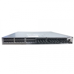
The choice between 800G and 400G optical transceivers is not simply a question of buying the faster module. AI-cluster networking must balance GPU density, fabric topology, switch-port availability, cabling reach, optics power, host-adapter capability, resiliency, and the time horizon of the deployment. A well-designed 400G fabric can be a better business decision than an unqualified 800G design, while an 800G design can reduce bottlenecks and port count when the entire path is ready. This guide explains how to make that choice methodically.
Begin with the application traffic model
Estimate the traffic generated by each node and by the cluster as a whole. Training workloads can create intensive east-west communication, checkpoint bursts, and storage traffic. Inference environments may need predictable latency and rapid scale-out rather than maximum peak bandwidth. Record GPU count per server, expected collective-communication pattern, storage design, target job size, desired oversubscription ratio, and redundancy policy. Use this information to calculate the required host-facing and spine-facing bandwidth. A transceiver speed does not provide value unless the NIC, switch port, PCIe path, and application can consume it.
Understand 400G and 800G as complete link ecosystems
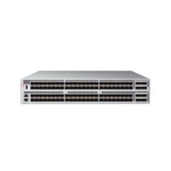
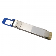
Both 400G and 800G can be delivered through different optical form factors, lane structures, reaches, and connector arrangements. The module, cable, switch cage, and remote endpoint must be selected together. Modern 800G switch systems may use OSFP or other high-density interfaces and may support breakout configurations, but the available modes are model-specific. A 400G link may use a different cage, connector, or fibre arrangement. For every link, document the physical interfaces at both ends, the lane mapping, the selected media, and the approved operating mode. Never assume that a simple mechanical adapter converts an unsupported link into a supported one.
Evaluate the topology and port economics
Higher-rate links can reduce the number of physical ports required for a given aggregate bandwidth, which may simplify a leaf-spine design and reduce cable count. They can also require newer switches, higher-power optics, and greater attention to cooling. A 400G fabric may take advantage of installed switch ports, existing cabling, or mature spare inventory. Compare designs by total usable bisection bandwidth, oversubscription, number of leaf and spine ports, expected growth, and the operational cost of spares. The best topology is the one that meets the workload requirement while preserving a clear expansion path.
Check the host side before committing to 800G
An 800G switch port is not a guarantee that every server can attach at 800G. Confirm the adapter card’s maximum throughput, port count, protocol, PCIe interface, host CPU topology, and approved cable or optic. Some designs use breakout connections from a higher-rate switch port to multiple lower-rate server links; these depend on the switch’s documented port mode and the correct splitter or transceiver assembly. Validate the complete host-to-switch path in a lab or pilot rack before ordering a full cluster bill of materials.
Power and thermal planning are design inputs
High-speed optical modules can consume more power than lower-rate alternatives, and a fully populated switch has a cumulative thermal load. Review the module power specification, switch-port power allowance, front-to-rear or rear-to-front airflow, rack cooling capacity, and adjacent-port guidance. Copper may be a useful option for short runs, but its reach, cable diameter, weight, and bend radius can become limiting at high port density. Optical designs require attention to fibre routing, connector cleanliness, polarity, and patching. Include these physical details in the rack design rather than adding them after switch delivery.
Performance qualification should include errors and recovery
Validate more than link-up. Test FEC settings, error counters, sustained throughput, tail latency, failover, and application behaviour under representative load. Capture transceiver telemetry, switch logs, NIC counters, and firmware versions. For an AI cluster, test a workload or benchmark that resembles the intended job size and communication pattern. A link that passes a short traffic test but accumulates errors under heat or load is not production-ready. Keep a baseline record so that future module replacements can be tested against known-good values.
Plan for serviceability and spares
Choose a module and cabling strategy that operations teams can identify, replace, and document. Standardise the approved part numbers per link type, label ports and fibre paths, and retain compatible spare optics in the correct form factor and reach. If 800G links are used at the spine, define how a failed module affects capacity and how traffic will reroute. If 400G links are used in a modular expansion, define when a new fabric tier is required. A resilient design includes both the normal operating state and the maintenance state.
Decision checklist
- Model workload bandwidth, topology, oversubscription, and growth before selecting a speed.
- Confirm switch, NIC, cable or optic, form factor, port mode, and firmware as an end-to-end path.
- Compare total port, optic, power, cooling, cabling, and spare costs.
- Validate representative traffic, error behaviour, and failover in a pilot.
- Document the approved bill of materials and replacement procedure.
Which speed is right?
Choose 400G when it meets the calculated workload requirement, matches a qualified infrastructure, and offers the best balance of capacity and operational simplicity. Choose 800G when the fabric, host adapters, and thermal design are ready to use it and the higher bandwidth improves the topology or expansion plan. Topstar can quote 400G and 800G optical options, but the final decision should follow an approved end-to-end compatibility and pilot-validation process.
