 dsale@topsfp.com
 العربية
 English
 русский
 español
 中文
中文



25G SFP28 optics are an interface decision, not a universal 5G module
25 Gigabit Ethernet is widely used for server connectivity, switch uplinks, storage paths, and selected mobile-network transport designs. It is often described loosely as a “25G optical module,” but a deployable link depends on much more than the nominal rate. The endpoint port, PHY mode, optical standard, fiber plant, reach, FEC setting, operating temperature, firmware, and network protocol must all be compatible.
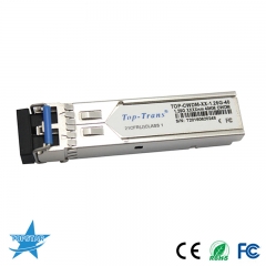
For most single-lane 25G optical Ethernet ports, the usual pluggable form factor is SFP28 rather than SFP+. The cages are physically related, but a 10G SFP+ optic should not be assumed to operate as a 25G interface, and a 25G SFP28 optic should not be assumed to work at 10G. Always use the port documentation and the manufacturer’s compatibility matrix for the exact NIC, switch, radio, or transport device.
Where 25G Ethernet fits in 5G and data-center networks
25G is a single-lane Ethernet technology that can provide a practical step above 10G for endpoint connectivity. The Ethernet Technology Consortium’s 25/50G specification explains the value of a single 25Gb/s lane for server and switch architectures, while the eCPRI specification lists 25GBASE-SR, LR, and ER among common optical Ethernet interface examples for eCPRI use cases. This does not mean that every 5G deployment requires 25G or that every SFP28 optic is suitable for a radio network. The radio vendor, fronthaul or midhaul architecture, functional split, bandwidth, timing design, and transport policy determine the real requirement.
In a data center, 25G can be used at server-facing ports with higher-speed uplinks or breakout designs. In a mobile network, it may be considered for Ethernet-based transport where the selected equipment and network design support it. Start with an interface document that defines the physical port, protocol, expected traffic, latency and synchronization requirements, protection method, and remote endpoint. The module is selected only after that information is clear.
Choose the optical interface from reach and fiber type
Do not choose a module simply because its label includes “25G.” Short-reach multimode interfaces, single-mode short-to-medium-reach interfaces, and longer-reach interfaces have different optical budgets, fiber requirements, connector types, and interoperability conditions. A project should identify the installed fiber type and condition, the number of connectors and patch panels, link loss, cleaning method, and planned margin before an optic is ordered.
For example, a 25GBASE-SR link is normally associated with multimode fiber and is used for relatively short structured links. 25GBASE-LR and 25GBASE-ER are single-mode optical interface families designed for different reach classes. The exact supported distance is not established by the transceiver name alone: it depends on the IEEE or vendor specification, the fiber grade, link loss, transmitter and receiver characteristics, and any system restrictions. Test or calculate the complete channel rather than using nominal cable length as the only decision factor.
Verify PHY link mode and FEC before deployment
25G interoperability can be affected by PHY link mode and forward-error-correction configuration. Intel’s 25G Ethernet media guide notes that 25GbE interoperability requires attention to IEEE and 25G/50G Consortium PHY link modes, as well as the media in use. A link may remain down, show errors, or operate unexpectedly if the NIC and switch use incompatible settings even when the correct form factor and wavelength appear to be installed.
For every connection, record the device model, port type, intended speed, configured and required FEC state, firmware and driver versions, and media part number. Confirm whether the port supports automatic negotiation, forced speed, breakout, or only specific qualified transceivers. Where the deployment includes eCPRI or another mobile-transport protocol, also verify VLAN, QoS, synchronization, and the relevant operator or equipment-vendor design rules. Do not treat an optical power reading as proof that the service layer is correctly configured.
Use a compatibility-first procurement record
A useful RFQ contains the information needed to prevent substitutions that look similar but are technically different. Name both endpoints, the exact port types, physical interface standard, fiber mode, connector polish, target reach, duplex or parallel-fiber structure, operating-temperature range, monitoring requirements, and any vendor coding or qualification rule. Add the desired quantity and a clear rule for whether matching vendor-coded optics, direct-attach cables, or active optical cables are acceptable.
For links that cross a building, a campus, or a third-party transport domain, include the complete channel map and loss budget. For data-center rows and racks, include the cable route and bend constraints. For radio or transport networks, include the traffic profile, timing requirements, protection path, and maintenance window. This evidence-based record is more reliable than buying by speed and connector alone.
Commission the link as a complete system
- Confirm the exact local and remote port models, supported optic list, software release, and configured speed.
- Verify the 25G physical interface, fiber type, connector type, channel length, and calculated or measured loss budget.
- Align PHY mode and FEC requirements at both ends, then record the final settings.
- Clean and inspect connectors, install the media, check link state and digital diagnostics where supported, and review error counters.
- Run traffic and service tests that reflect the intended application before the link is accepted into production.
Reference standards and device documentation
Standards and consortium documents explain the technology, but the exact equipment vendor’s documentation is the final authority for a particular port. Treat reach, interoperability, and supported media as configuration-specific. Recheck the current compatibility matrix whenever a switch, NIC, radio, firmware, or optical module revision changes.
Primary technical references: Ethernet Technology Consortium 25/50G Ethernet specification, Intel 25G Ethernet Media Guide, and the eCPRI physical-layer specification. Consult the current data sheet and compatibility list for the exact optical module before purchase or installation.
